Saturday 11 November 2017

ISO 26262 Part 6.7: Software Architectural Design - Detailed Explanation (Part 3/4)

ISO 26262 Part 6.7: Software Architectural Design - Detailed Explanation (Part 3/4)


This blog is an continuation of the previous blog with the following link

Error Handling Mechanisms

ISO 26262-6:2011(E) – Clause 7.4.15:
*** Please refer this clause from originally procured licensed copy of ISO26262 Part 6*** 


ISO 26262-6:2011(E) – Clause 7.4.15: Understanding


  • Error handling refers to parking the functionality into the normal state or to safe state once the fault is detected.
    • Static recovery mechanism
      • Static recovery mechanism refers to actions that is decided before the software runs. For example the software reset after watchdog fault detection is a predefined action provided by the microcontroller. While sometimes it is possible to handle some interrupt at 75% of watchdog reset time before the actual watchdog reset happens. During this interrupt some steps like storing data in Keep Alive Memory (KAM) can be done.
    • Graceful degradation
      • Degradation refers to the systems running under reduced functionalities or performance or both.
      • For example in case of fault is detected in the host IC then the host IC might shutdown the power to other modules/ICs and stay in sleep/dormant state as a safe state.
    • Independent parallel redundancy
      • A redundant method may be applied as a backup for the main path. In case of failure of the main path, the second redundant path kicks in and keeps the system running.
    • Correcting codes for data
      • Sometimes there are mechanisms where the error if detected can be corrected by means of adding redundant data as a level of protection.
      • For example the features like Single bit Error Detection and Correction and Double bit Error Detection (SECDED) are now available in microcontrollers.

ISO 26262-6:2011(E) – Clause 7.4.16:
*** Please refer this clause from originally procured licensed copy of ISO26262 Part 6*** 

ISO 26262-6:2011(E) – Clause 7.4.16: Understanding

  • Sometimes the software architectural design may leads to constraints that cannot be resolved by safety mechanisms. This may result in hazards. This is evident from the safety analysis. In a reverse way this may lead to addition or modification of the original safety goal. IN such case the change management should be invoked to edit all the work products starting from the concept phase.

ISO 26262-6:2011(E) – Clause 7.4.17:
*** Please refer this clause from originally procured licensed copy of ISO26262 Part 6*** 

ISO 26262-6:2011(E) – Clause 7.4.17: Understanding

  • The detailed analysis for the available resources like memory, task scheduling should be designed.
  • The memory map should be designed considering the allowed memory consumptions, functionalities, safety/non safety SW components etc.
  • The task timings should be determined based upon functionalities, resource dependencies, sequence of data flow etc.

(...Continued in Next Part)

ISO 26262 Part 6.7: Software Architectural Design - Detailed Explanation (Part 2/4)

ISO 26262 Part 6.7: Software Architectural Design - Detailed Explanation (Part 2/4)

Introduction:

This blog is an continuation of the previous blog with the following link

Notations for Software Architectural Design (SAD):


ISO 26262-6:2011(E) – Clause 7.4.6, 7.4.7, 7.4.8:
*** Please refer this clause from originally procured licensed copy of ISO26262 Part 6*** 

ISO 26262-6:2011(E) – Clause 7.4.6, 7.4.7, 7.4.8: Understanding

  • Each SW component should be defined as whether it is developed from scratch, or reused with or without modifications.
  • Based upon this the work products can be reused or freshly created.

Allocation of ASIL Levels:


ISO 26262-6:2011(E) – Clause 7.4.9, 7.4.10:
*** Please refer this clause from originally procured licensed copy of ISO26262 Part 6*** 

ISO 26262-6:2011(E) – Clause 7.4.9, 7.4.10: Understanding

  • Once the SW/FW Elements is broken down into multiple SW Components, Sub-Components and Functionalities, it might happen that they may not be all safety related. 
  • A safety related SW Sub-Component might have multiple SW functionalities which may or may not be safety related. Even the level of ASIL of these functionalities might differ. In case there is difference in the level of ASILs then the SW development should be done with the highest ASIL level within that component,
  • In case you don’t want to use highest ASIL level as the base of development for SW Functionalities or don’t want any particular functionality to be safety based then you have to prove in-dependency through Dependent Failure Analysis (DFA).


Safety Analysis:


ISO 26262-6:2011(E) – Clause 7.4.11:
*** Please refer this clause from originally procured licensed copy of ISO26262 Part 6*** 

ISO 26262-6:2011(E) – Clause 7.4.11: Understanding

  • One of the best way to ensure the Freedom Of Interference in the SW component are as follows:
    • Use separate micro controller handling independent functionalities.
      • Ensures no dependencies except for the power supply in case in the same PCB.
    • Use separate cores in the same micro controller handling independent functionalities.
      • Some dependencies still persists like the common shared area, data or memory bus or peripherals like timer.
    • Use separate memory sections (for code and data) handling independent functionalities.
      • Though the code and data are located in different memory locations still the memory is common, any defect will affect both of the functionalities.
      • The data and memory bus for accessing the data will be common hence a lot of dependency will be their which needs other methods to prove independence like applying safety mechanisms on memory, data bus
ISO 26262-6:2011(E) – Clause 7.4.12:
*** Please refer this clause from originally procured licensed copy of ISO26262 Part 6*** 

ISO 26262-6:2011(E) – Clause 7.4.12: Understanding

  • The Dependency Failure Analysis (DFA) should also look into factors like Cascading and Common Cause Failures.
  • The Dependency Failure Analysis (DFA) can be analysed from following 2 points
    • Freedom from Interference (FFI)
    • Independency
  • Freedom from Interference (FFI) between SW components should also be analysed from following points.
    • Timing and Executions
    • Memory
    • Exchange of Information
  • Please refer my previous blog below for further details on DFA. ISO 26262 - Dependent Failure Analysis (DFA)

ISO 26262-6:2011(E) – Clause 7.4.13:
*** Please refer this clause from originally procured licensed copy of ISO26262 Part 6*** 

ISO 26262-6:2011(E) – Clause 7.4.13: Understanding

  • The FTA (Fault Tree Analysis) and FMEA (Failure Mode Effect Analysis) should be done on the basis of SW architectural elements. In case any failure detected it needs to be justified or safety mechanism needs to be added.

Safety Mechanism:

ISO 26262-6:2011(E) – Clause 7.4.14:
*** Please refer this clause from originally procured licensed copy of ISO26262 Part 6*** 


ISO 26262-6:2011(E) – Clause 7.4.14: Understanding
  • The FTA (Fault Tree Analysis) and FMEA (Failure Mode Effect Analysis) should be done on the basis of SW architectural elements. In case any failure detected it needs to be justified or safety mechanism needs to be added.
    • Range checks of input and output data
      • From the list of interfaces (both input and output) defined in the architecture design, the range check can be used as a safety mechanism.
      • However it doesn’t ensure detection of failures within the range.
    • Plausibility check
      • The plausibility check is carried out to check the validity of the data from multiple sources.
      • For example in case the voltage needs to be measured from a point, then it can be measured through ADC channel or a small circuit can be added to convert the DC voltage to PWM signal, This PWM signal can measured based on high and low period to determine the voltage. Hence plausibility check is based upon 2 different sources of signals.
    • Detection of data errors
      • The data errors are detected by methods like RAM ECC checks, Peripherals ECC checks and Flash ECC checks.
      • The detection style may be Single bit Error Detection and Correction and Double bit Error Detection (SECDED) based upon the feature available in the micro-controller.
    • External monitoring facility
      • External monitoring can be implemented by constantly monitoring the SW within a micro-controller.
      • Pair of Micro-controllers like Power Management IC and the Host IC has been developed as a method of external monitoring facility.


    • Control flow monitoring
      • Reference: https://vector.com/portal/medien/cmc/press/Vector/AUTOSAR_TTTech_ElektronikAutomotive_201204_PressArticle_EN.pdf
      • As per the above document from Vector.
        • The Safe Watchdog Manager (SWdgM) is the safety mechanism that is responsible for timing and program flow monitoring. Safety-relevant functions are monitored to ensure that the functions are executed in their correct sequential flow.
        • Checkpoints in all relevant software components regularly report to the Safe Watchdog Manager on the program flow.
        • This enables reliable detection of all types of run time interference.
        • If an application, interrupt or function is not activated in a timely manner, the Safe Watchdog Manager detects this and initiates a reaction to the error. 
        • Along with time duration, correct sequence in the program flow is also monitored.


      • Diverse software design
          • Diverse design of SW components can be developed so that the output of each can be compared to detect any mismatch between them. Once the mismatch id detected the system can be set to safety state.
        (...Continued in Next Part)


        Tuesday 7 November 2017

        ISO 26262 Part 6.7: Software Architectural Design - Detailed Explanation (Part 1/4)

        ISO 26262 Part 6.7: Software Architectural Design - Detailed Explanation (Part 1/4)

        Introduction:

        This blog tries to explain the clauses in Software Architectural Design (SAD) in detail. After that a sample template for the SAD is given for reference. This template for SAD tries to capture all the requirements from ISO26262 Part 6.7, however the reader might add/ delete any section as required.

        In order to save the readers from a long blog, this blog has been divided into 4 Parts based on the clauses and their categories. All the clauses in ISO 26262-6:2011(E) can be grouped into following categories based upon their applicability.


        ISO 26262-6:2011(E) Clauses
        Applicability/ Categories
        Covered in which part of this Blog?
        -
        Introduction
        ISO 26262 Part 6.7: Software Architectural Design - Detailed Explanation (Part 1/4)
        Clause 7.4.1
        Notations for Software Architectural Design (SAD)
        Clause 7.4.2, Clause 7.4.3, Clause 7.4.4, Clause 7.4.5
        Principles of software architectural design
        Clause 7.4.6, Clause 7.4.7, Clause 7.4.8
        Category of software components
        ISO 26262 Part 6.7: Software Architectural Design - Detailed Explanation (Part 2/4)
        Clause 7.4.9, Clause 7.4.10
        Allocation of ASIL level
        Clause 7.4.11, Clause 7.4.12, Clause 7.4.13
        Safety Analysis
        Clause 7.4.14
        Safety Mechanism
        Clause 7.4.15
        Error handling mechanism
        ISO 26262 Part 6.7: Software Architectural Design - Detailed Explanation (Part 3/4)
        Clause 7.4.16
        Change requests arising from design activity
        -
        Sample SAD template
        ISO 26262 Part 6.7: Software Architectural Design - Detailed Explanation (Part 4/4)

        * References are mentioned in the last part.

        Notations for Software Architectural Design (SAD):

        ISO 26262-6:2011(E) – Clause 7.4.1:

        *** Please refer this clause from originally procured licensed copy of ISO26262 Part 6*** 

        ISO 26262-6:2011(E) – Clause 7.4.1: Understanding

        1a. Informal notations:

        • Informal notations refers to plain basic/natural language.

        1b. Semi-formal notations:

        • Semi-formal notations refers to plain basic/natural language along with pictorial/diagrammatically way of representations.
        • This will include
          • System design diagrams (Hierarchical Design)
          • Data Flow Diagram (External Software Design, Internal Software Design)
          • Sequence Diagrams
          • Flow Charts
          • Software Code Structure (Driver, Middle, Application etc.)
          • Call Hierarchy
        1c. Formal notations:

        • Formal notations refers to mathematical expressions like design through MATLAB design.
        • These MATLAB design can be later verified through formal verification methods.

        Principles for Software Architectural Design (SAD):

        ISO 26262-6:2011(E) – Clause 7.4.2:
        *** Please refer this clause from originally procured licensed copy of ISO26262 Part 6*** 
        ISO 26262-6:2011(E) – Clause 7.4.2: Understanding
        • The various Design Principles are listed below.
          • Design Principle 1: System design diagrams (Hierarchical Design)
          • Design Principle 2: Data Flow Diagram (External Software Design, Internal Software Design)
          • Design Principle 3: Sequence Diagrams
          • Design Principle 4: Flow Charts
          • Design Principle 5: Software Code Structure (Driver, Middle, Application etc.)
          • Design Principle 6: Call Hierarchy
        • The above Design Principles are mapped against their applicability for the points mentioned in the Clause 7.4.2.

        ISO 26262-6:2011(E) – Clause 7.4.3:
        *** Please refer this clause from originally procured licensed copy of ISO26262 Part 6*** 


        ISO 26262-6:2011(E) – Clause 7.4.3: Understanding
        • 1a. Hierarchical structure of software components:
          • This is achieved by breaking the large size design blocks into smaller ones.
          • System Level SW Elements -> SW Components -> SW Sub Components -> SW Functionality -> SW Unit Functions
          • These blocks needs to be created based upon the modularity, independency and testability.
        • 1b. Restricted size of software components:
          • Software blocks should be decided based upon their independent identities and functionalities
          • Only when this independency is maintained it will be easier in future to propose/implement any particular safety mechanism for the block in case need arises.
        • 1c. Restricted size of interfaces:
          • The size and kind of data to be exchanged between various SW blocks must be limited
          • Every interface signal needs to be analysed from the point of Safety Analysis (FTA, FMEA) and Dependent Failure Analysis. Hence more the interfaces higher is the chances of Failure arising due to exchange of data.
        • 1d. High cohesion within each software component:
        • 1e. Restricted coupling between software components:
          • The high cohesion of the SW block is decided based upon the functionality to be implemented.
          • The SW block should be independent enough to be verifiable.
          • By this principle the independency between the main implementation path and redundant (safety mechanism) path can be maintained.
        • 1f. Appropriate scheduling properties:
          • The sequence of data exchange between the SW blocks depends upon the origin and time taken for processing the data.
          • Hence proper scheduling of data needs to be maintained.
          • For example in case the ADC data conversion SW block (1) is done in 5msec, then the temperature determination SW block (2) should be scheduled after (1) or scheduled at a lower frequency (like 10msec) so that ADC data is available for processing.
        • 1g. Restricted use of interrupts:
          • The interrupt based handling causes SW to jump to different locations very frequently and may result in undesired behaviour if not correctly handled.
          •  It may also affect the scheduling sequence of the SW, hence it is advised to avoid interrupt based handling and prefer the polling based handling.
          • Polling based handling gives more control for the flow of the software.
        ISO 26262-6:2011(E) – Clause 7.4.4:
        *** Please refer this clause from originally procured licensed copy of ISO26262 Part 6*** 

        ISO 26262-6:2011(E) – Clause 7.4.4: Understanding
        • The SW Architecture must detail down the blocks until its implementation by SW functions.
        • This assignment of SW functions to each blocks provides the linkage between the SW Architecture Design phase and SW Detailed Design phase.
        • The detailed block wise explanation for hierarchy has already been explained in previous blog : ISO 26262 Hierarchical Components - A Software Perspective

        ISO 26262-6:2011(E) – Clause 7.4.5:
        *** Please refer this clause from originally procured licensed copy of ISO26262 Part 6*** 

        ISO 26262-6:2011(E) – Clause 7.4.5: Understanding

        Static Design Aspects:
        The Design Aspects which comes to picture while the software is not being executed are called Static Design Aspects.
        • The software structure including its hierarchical levels
          • As explained in the above this part must contain the hierarchical breakdown of the major blocks starting from the
            • Concept level – Items/ Systems/ Subsystems,
            • System level – HW/ SW/ FW elements
            • Software level – SW Components/ Sub-Components/ Functionalities/ Unit functions.
          • In the SW Architecture Design document this section comes first where this break down is shown with each SW system level elements.
        • The logical sequence of data processing:
          • At the System level, during the System Design the HW/SW/FW elements are shown to interact with each other using data/signals.
          • The sequence of data flow is based upon the functionality of the SW block.
        • The data types and their characteristics;
          • The interfaces their type and their values needs to be defined in the External Software Design diagram.
          • The direction of the interface is also mentioned.
          • The interfaces should be defined based upon optimum utilization of available resources like memory.
        • The external interfaces of the software components;
        • The external interfaces of the software; and
          • The software blocks interact with other blocks that may be within same functionalities or blocks outside the functionalities through data interfaces.
          • For example if calibration SW block can provide the data interface for Temperature Monitoring enable/ disable data signal to Temperature Monitoring SW block.
        • The constraints including the scope of the architecture and external dependencies.
          • Sometimes the SW blocks created has dependencies on other SW blocks that may or may not be part of analysis.
          • For example if an ECU1 for which the ISO 26262 based designing is being done, depend on another ECU2 for data through CAN channel. Hence the SW Architecture Design document should note that the analysis of ECU2 is not under scope and it has dependency on the CAN signal as an external interface. So it might not be required to check the integrity of this external interface data assuming it would be received properly.

        Dynamic Design Aspects:
        The Design Aspects which comes to picture while the software is being executed are called Dynamic Design Aspects.
        • The functionality and behaviour;
          • Of course the division of the SW blocks are made from the primary aim of functionalities and the role they are going to play.
        • The control flow and concurrency of processes;
          • The control flow of the software functionalities are decided by their call tree beginning at the Task Scheduling.
          • Hence a section should be present in the Software Architectural Design document containing all the scheduling happening and the tasks (like 1msec, 5msec, 10msec etc.) from where rest of the functions called.
          • Though this section would also reappear when the design for the “OS scheduler” SW component is created.
        • The data flow between the software components;
        • The data flow at external interfaces;
          • The data flow between the other SW blocks is explained along with their properties and range of values.
        • The temporal constraints.
          • In case the data interfaces are time based, then proper justification should be provided for determining the frequency of the call for the SW block in the design.
          • Below are the examples where temporal constraints needs to be considered during design formulation.
            • Sometimes temporal constraints arises due to polling of some microcontroller registers where you have for the registers to be set (like waiting for the PLL to lock in a while loop). Designing come to picture in such scenario when you have to design time out of the while loop.
            • Temporal constraint also arises when you have to implement a power on sequence, where in the microcontrollers and others ICs (like the ECU, power supply, CAN transceivers etc.) have to power on in a particular sequence of events.
        Both the static and dynamic design aspects reflects in the design principles that were earlier explained. Hence the coverage of each aspect through design principles is explained below.


        (...Continued in Next Part)

        Sunday 5 November 2017

        ISO 26262 Hierarchical Components - A Software Perspective

        ISO 26262 Hierarchical Components - A Software Perspective

        Introduction:

        The hierarchy in ISO26262 based design begins from the Concept Phase. At every part the components are broken down further to reach the lowest unit of implementation. 

        For example the lowest unit for Software are the functions while that of the hardware are hardware components like resistors, capacitors etc.

        In the below section the hierarchical components are explained in details from software perspective.The probable ID of each blocks are also suggested so that they can be linked and tracked upstream and down stream.

        The basic hierarchy for deriving the SW architecture modules is shown as below.

        Phase wise distribution of components:


        ISO Part
        Section No.
        Work product details
        Description
        Part 3: Concept Phase
        3.5
        Item Definition
        Define the Item at the vehicle level
        Part 4: Product development at the system level
        4.6
        Specification of technical safety requirements
        Define the System Level Elements, which can be Hardware (HW) Elements, Software (SW) Elements or Firmware (FW) Elements
        4.7
        System design
        Part 6: Product development at the system level
        6.7
        Software architectural design
        Each Software (SW) Elements or Firmware (FW) Elements is divided into
        ·         Software Component (SWC)
        ·         Software Sub-Component (SSWC)
        ·         Firmware Component (FSWC)
        ·         Firmware Sub-Component (FSWC)
        Each SWC or FWC is further divided into
        ·         Software Functionality (SF)
        ·         Firmware Functionality (FF)
        6.8
        Software unit design and implementation
        Each Software Functionality (SWF) or Firmware Functionality (FWF) is divided into
        ·         Software Unit functions (SUF)
        ·         Firmware Unit functions (FUF)

        Concept, System Level Hierarchy:

        Basic structure:


        Example:


        Software Level Hierarchy:

        Basic structure:


        Sunday 19 February 2017

        3.3V and 5V from 12V Supply using LM317


        As already explained in the earlier blog entry EmbeddedInEmbedded: LM317 regulator : 3.3V Power supply for Micro-Cont... the below project is created for hardware implementation.

        In this power supply board the 12V DC voltage is converted to 3.3V and 5V separately that can be used for various purposes like supply to development boards, micro controller etc.

        The list of components used are listed:

        12V to 3.3V Converter:
        - Heat Sink (with screw)
        - LM317T Regulator (1.2V to 37V Regulator) (LM317 Details)
        - Capacitors (10uF, 100uF Electrolytic capacitor)
        - Resistance (330 Ohms, 560 Ohms)

        12V to 5V Converter:
        - Heat Sink (with screw)
        - LM317T Regulator (1.2V to 37V Regulator) (LM317 Details)
        - Capacitors (10uF, 100uF Electrolytic capacitor)
        - Resistance (220 Ohms, 680 Ohms)

        Others:
        - LEDs (3)
        - MX-27 DC Jack
        - General purpose PCB board
        - Switch (2)
        - Berg strips (female) for connections

        Schematic 1: 3.3V


        Schematic 2: 5V


        PCB board with only switches for 2 separate modules.


        The input 12V is indicated through a red LED.


        The 3.3V module is added on the PCB board.


        The 5V module is added on the PCB board.


        The rear side of the PCB board.


        The 3.3V and 5V modules are active, indicated by 2 green LEDs.


        The board functioning is shown in the video attached below.


        Sunday 5 February 2017

        ISO 26262 - Dependent Failure Analysis (DFA)

        ISO 26262 - Dependent Failure Analysis (DFA):


        Dependent failure analysis aims at identifying failures that may hamper the required independence or freedom from interference between given elements (hardware/ software/ firmware) which may ultimately lead to violation of safety requirement or safety goal.

        Hence Dependent Failure Analysis consists of following 2 parts.
        • Validate Freedom from Interference (FFI) between elements.
        • Validate Independence between elements


        Difference between Common Cause Failures and Cascading Failures:

        Cascading Failures:

        • Failure of an element of an item results in failure of another element or element of the same to fail.
        • Cascading failures are dependent failure that are not common cause failures.

        Common Cause Failures:

        • Failure of 2 or more elements of an item resulting from single specific event or root cause.
        • Common cause failures are dependent failure that are not cascading failures.


        Dependent failure types:

        Dependent Failures can arise from systematic failures and random hardware failures.


        How to identify Dependent Failure Analysis?


        Dependent Failures can be identified from Safety Analysis.

        Deductive analyses:


        • Examination of cut sets or repeated identical events of an FTA can indicate potential for dependent failures.

        Inductive analyses:

        • Similar parts or components with similar failure modes that appear several times in an FMEA can give additional information about the potential for dependent failures.


        DFA Part 1: Freedom from Interference (FFI):

        Analysis of interactions between software elements:

        • The FFI should be analyzed between software elements (determined during software architecture design).
        • Since the FFI is based upon analysis of only cascading failure, hence the data exchange between software elements should be analyzed.
        • The ASIL level of software elements (source and destination elements) between which data exchange takes should be analyzed.
        • In case the data exchange occurs between originating from lower level ASIL element to higher level ASIL element, then such interactions should be marked for analysis.
        • These data exchanges should be analyzed for freedom from independence.
        • In case plausibility is proved then mechanisms to prevent, detect and mitigate relevant faults are assessed during analysis.

        Analyze the interaction between software elements for following possible failures.

        Timing and Execution:

        • blocking of execution.
        • deadlocks – several processes blocking mutually by waiting for events that can be triggered by themselves.
        • Livelocks – several processes keeping each other in infinite loop.
        • incorrect allocation of execution time.
        • incorrect synchronization between software elements.

        Memory:

        • corruption of content.
        • read or write access to memory allocated to another software element.

        Exchange of Information:


        • repetition of information.
        • loss of information.
        • delay of information.
        • insertion of information.
        • masquerade or incorrect addressing of information.
        • incorrect sequence of information.
        • corruption of information.
        • asymmetric information sent from a sender to multiple receivers.
        • information from a sender received by only a subset of the receivers.
        • blocking access to a communication channel.

        Table 1: Analysis of interaction between software elements for possible failures.


        Table 2: Analysis of interaction between software elements for possible failures.

        DFA Part 2: Independence


        Identification of couples:


        Based upon above factors architectural units can be identified to form couples to prove independence amongst them. 
        The couples can be identified based upon following factors.
        • Similar and dissimilar redundant elements
        • Different functions implemented with identical software or hardware elements
        • Functions and their respective safety mechanisms
        • Partitions of functions or software elements
        • Physical distance between hardware elements, with or without barrier
        • Common external resources

        The above criteria are described in details.


        Similar and dissimilar redundant elements


        In this example, 2 redundant software functionalities are implemented using different algorithms to provide an output (SO1 - which is Safety related).

        SWF1: Multiplication using actual multiplication operatorSWF2: Multiplication using repeated addition operator

        So, to determine the integrity of this output (SO1), both SWF1 and SWF2 needs to be identified as a couple. These can form a couple since they are used to provide a single output, which may fail due to following reasons.

        SWF1 block failure (like SWF1 function not completely called due to interrupt function call, memory corruption of the code flash area where SWF1 or any of its variable is stored etc.). Similar in case of SWF2.

        Different functions implemented with identical software or hardware elements


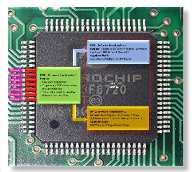
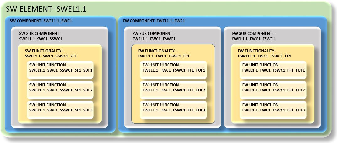
        In this example, 2 different software functionalities (SWF1, SWF2) are using same Firmware functionality (FWF1) algorithms to get the battery voltage and power source voltage for ECU2 from a common functionality (FWF1).

        Both the software functionalities are implemented using a common/identical firmware element i.e. ADC firmware. Hence both these software elements can be considered as a couple.


        In this example, the Power IC determines the voltage and current flowing through the Line and Neutral. Then the IC sends the values through SPI line to the Main micro controller for processing.

        In this example, 2 different software functionalities (SWF2, SWF3) are using SPI driver firmware functionality (FWF1) to get the raw voltage and current values.

        Both software functionalities (SWF2, SWF3) are then using the square functionality (SWF1) to determine the RMS voltage and current.

        Since both SWF1 and SWF2 are different functions implemented through same software element (FWF1) hence both can be considered as a couple.

        Functions and their respective safety mechanisms


        In this example, the software functionality (SWF1) controls the Relay control IC (1,2) for live and neutral. The software functionality (SWF2) is used to detect the feedback from the voltage/current monitoring IC that monitors the flow of current. Hence once SWF1 controls the relay to stop current flow. SWF2 acts a safety mechanism for SWF1.

        So, both SWF1 and SWF2 can be identified as a couple for analysis to check if there is any dependency.

        Partitions of functions or software elements


        In this example, SWF1 is Non-Safety related functionality that is located in block 1 of flash memory. SWF2 is Safety related functionality that is located in block 2 of flash memory. Both share data through a shared memory section accessible to both blocks. In case of modification of QM functionality will not affect ASIL level implementation. Such functionalities can be treated as a couple for analysis. Factors such as any impact while reading data from common memory should be analyzed for these couple.

        Physical distance between hardware elements, with or without barrier


        In this example, 2 hardware elements are under consideration (HWEL1, HWEL2). The Main microcontroller (HWEL1) controls the relay on off through the Relay Control IC (HWEL2). The Relay Control IC and Relays are so designed that in case of below scenarios the Relays are off. 

        1. Power Failure to both Relay Control IC or Main Microcontroller
        2. Relay Control IC Failure
        3. Main Microcontroller IC failure (or Main Microcontroller is not able to communicate with Relay Control IC)

        SO here in case of a hypothetical scenario when the main microcontroller gets fried due to a very high EMI/EMC radiation and the relays are not under control of the Main Microcontroller, the Relays should be in off state, so that the switches are closed. Hence here both HWEL1 and HWEL2 should be considered as a couple for analysis.

        Common external resources


        In this example, the signals like ignition, VSS (Vehicle Speed Sensor), RPM (Rotation per Minute) etc. are received from external sources for EPS module. The software functionalities within EPS module can use this external sources data for computation, hence these can form couples.


        Table 3: Couple identifications


        Dependent failures should be identified for the identified couples.
        These potential failures should be identified for their plausibility of violation of independence.


        Table 4: Failure type identification


        Table 5: Detailed Analysis