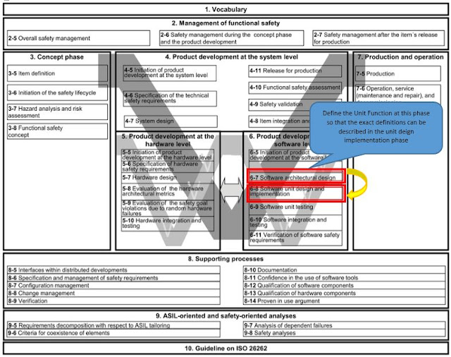
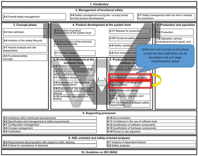
ISO 26262 Part 6.7: Software Architectural Design - Detailed Explanation (Part 1/4)
Introduction:
This blog tries to explain the clauses in Software Architectural Design (SAD) in detail. After that a sample template for the SAD is given for reference. This template for SAD tries to capture all the requirements from ISO26262 Part 6.7, however the reader might add/ delete any section as required.
In order to save the readers from a long blog, this blog has been divided into 4 Parts based on the clauses and their categories. All the clauses in ISO 26262-6:2011(E) can be grouped into following categories based upon their applicability.
ISO 26262-6:2011(E) Clauses
|
Applicability/ Categories
|
Covered in which part of this Blog?
|
-
|
Introduction
|
ISO 26262 Part 6.7: Software Architectural Design - Detailed
Explanation (Part 1/4)
|
Clause 7.4.1
|
Notations for Software Architectural Design (SAD)
|
|
Clause 7.4.2, Clause 7.4.3, Clause 7.4.4, Clause 7.4.5
|
Principles of software architectural design
|
|
Clause 7.4.6, Clause 7.4.7, Clause 7.4.8
|
Category of software components
|
ISO 26262 Part 6.7: Software Architectural Design - Detailed
Explanation (Part 2/4)
|
Clause 7.4.9, Clause 7.4.10
|
Allocation of ASIL level
|
|
Clause 7.4.11, Clause 7.4.12, Clause 7.4.13
|
Safety Analysis
|
|
Clause 7.4.14
|
Safety Mechanism
|
|
Clause 7.4.15
|
Error handling mechanism
|
ISO 26262 Part 6.7: Software Architectural Design - Detailed
Explanation (Part 3/4)
|
Clause 7.4.16
|
Change requests arising from design activity
|
|
-
|
Sample SAD template
|
ISO 26262 Part 6.7: Software Architectural Design - Detailed
Explanation (Part 4/4)
|
* References are mentioned in the last part.
Notations for Software Architectural Design (SAD):
ISO 26262-6:2011(E) – Clause 7.4.1:
*** Please refer this clause from originally procured licensed copy of ISO26262 Part 6***
ISO 26262-6:2011(E) – Clause 7.4.1: Understanding
1a. Informal notations:
1b. Semi-formal notations:
*** Please refer this clause from originally procured licensed copy of ISO26262 Part 6***
1a. Informal notations:
- Informal notations refers to plain basic/natural language.
1b. Semi-formal notations:
- Semi-formal notations refers to plain basic/natural language along with pictorial/diagrammatically way of representations.
- This will include
- System design diagrams (Hierarchical Design)
- Data Flow Diagram (External Software Design, Internal Software Design)
- Sequence Diagrams
- Flow Charts
- Software Code Structure (Driver, Middle, Application etc.)
- Call Hierarchy
- Formal notations refers to mathematical expressions like design through MATLAB design.
- These MATLAB design can be later verified through formal verification methods.
Principles for Software Architectural Design (SAD):
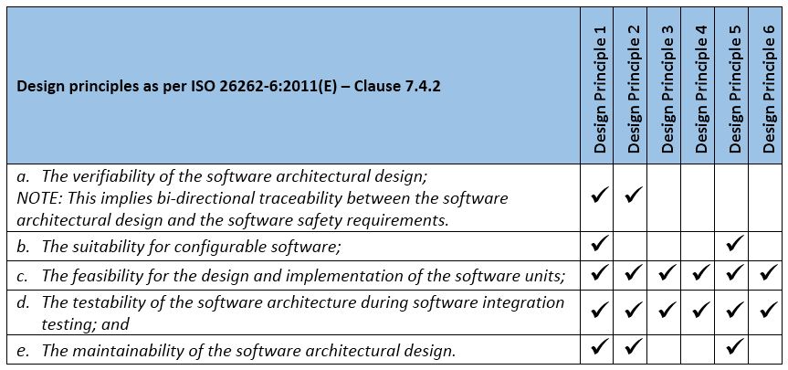
ISO 26262-6:2011(E) – Clause 7.4.2:*** Please refer this clause from originally procured licensed copy of ISO26262 Part 6***
ISO 26262-6:2011(E) – Clause 7.4.2: Understanding


- The various Design Principles are listed below.
- Design Principle 1: System design diagrams (Hierarchical Design)
- Design Principle 2: Data Flow Diagram (External Software Design, Internal Software Design)
- Design Principle 3: Sequence Diagrams
- Design Principle 4: Flow Charts
- Design Principle 5: Software Code Structure (Driver, Middle, Application etc.)
- Design Principle 6: Call Hierarchy
- The above Design Principles are mapped against their applicability for the points mentioned in the Clause 7.4.2.
ISO 26262-6:2011(E) – Clause 7.4.3:
*** Please refer this clause from originally procured licensed copy of ISO26262 Part 6***

ISO 26262-6:2011(E) – Clause 7.4.3: Understanding
- 1a. Hierarchical structure of software components:
- This is achieved by breaking the large size design blocks into smaller ones.
- System Level SW Elements -> SW Components -> SW Sub Components -> SW Functionality -> SW Unit Functions
- These blocks needs to be created based upon the modularity, independency and testability.
- 1b. Restricted size of software components:
- Software blocks should be decided based upon their independent identities and functionalities
- Only when this independency is maintained it will be easier in future to propose/implement any particular safety mechanism for the block in case need arises.
- 1c. Restricted size of interfaces:
- The size and kind of data to be exchanged between various SW blocks must be limited
- Every interface signal needs to be analysed from the point of Safety Analysis (FTA, FMEA) and Dependent Failure Analysis. Hence more the interfaces higher is the chances of Failure arising due to exchange of data.
- 1d. High cohesion within each software component:
- 1e. Restricted coupling between software components:
- The high cohesion of the SW block is decided based upon the functionality to be implemented.
- The SW block should be independent enough to be verifiable.
- By this principle the independency between the main implementation path and redundant (safety mechanism) path can be maintained.
- 1f. Appropriate scheduling properties:
- The sequence of data exchange between the SW blocks depends upon the origin and time taken for processing the data.
- Hence proper scheduling of data needs to be maintained.
- For example in case the ADC data conversion SW block (1) is done in 5msec, then the temperature determination SW block (2) should be scheduled after (1) or scheduled at a lower frequency (like 10msec) so that ADC data is available for processing.
- 1g. Restricted use of interrupts:
- The interrupt based handling causes SW to jump to different locations very frequently and may result in undesired behaviour if not correctly handled.
- It may also affect the scheduling sequence of the SW, hence it is advised to avoid interrupt based handling and prefer the polling based handling.
- Polling based handling gives more control for the flow of the software.
ISO 26262-6:2011(E) – Clause 7.4.4:
*** Please refer this clause from originally procured licensed copy of ISO26262 Part 6***
ISO 26262-6:2011(E) – Clause 7.4.4: Understanding
- The SW Architecture must detail down the blocks until its implementation by SW functions.
- This assignment of SW functions to each blocks provides the linkage between the SW Architecture Design phase and SW Detailed Design phase.
- The detailed block wise explanation for hierarchy has already been explained in previous blog : ISO 26262 Hierarchical Components - A Software Perspective
ISO 26262-6:2011(E) – Clause 7.4.5:
*** Please refer this clause from originally procured licensed copy of ISO26262 Part 6***
ISO 26262-6:2011(E) – Clause 7.4.5: Understanding
Static Design Aspects:
The Design Aspects which comes to picture while the software
is not being executed are called Static Design Aspects.
- The software structure including its hierarchical levels
- As explained in the above this part must contain the hierarchical breakdown of the major blocks starting from the
- Concept level – Items/ Systems/ Subsystems,
- System level – HW/ SW/ FW elements
- Software level – SW Components/ Sub-Components/ Functionalities/ Unit functions.
- In the SW Architecture Design document this section comes first where this break down is shown with each SW system level elements.
- The logical sequence of data processing:
- At the System level, during the System Design the HW/SW/FW elements are shown to interact with each other using data/signals.
- The sequence of data flow is based upon the functionality of the SW block.
- The data types and their characteristics;
- The interfaces their type and their values needs to be defined in the External Software Design diagram.
- The direction of the interface is also mentioned.
- The interfaces should be defined based upon optimum utilization of available resources like memory.
- The external interfaces of the software components;
- The external interfaces of the software; and
- The software blocks interact with other blocks that may be within same functionalities or blocks outside the functionalities through data interfaces.
- For example if calibration SW block can provide the data interface for Temperature Monitoring enable/ disable data signal to Temperature Monitoring SW block.
- The constraints including the scope of the architecture and external dependencies.
- Sometimes the SW blocks created has dependencies on other SW blocks that may or may not be part of analysis.
- For example if an ECU1 for which the ISO 26262 based designing is being done, depend on another ECU2 for data through CAN channel. Hence the SW Architecture Design document should note that the analysis of ECU2 is not under scope and it has dependency on the CAN signal as an external interface. So it might not be required to check the integrity of this external interface data assuming it would be received properly.
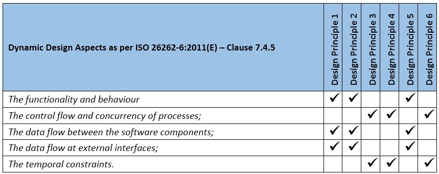
Dynamic Design Aspects:
The Design Aspects which
comes to picture while the software is being executed are called Dynamic Design
Aspects.
- The functionality and behaviour;
- Of course the division of the SW blocks are made from the primary aim of functionalities and the role they are going to play.
- The control flow and concurrency of processes;
- The control flow of the software functionalities are decided by their call tree beginning at the Task Scheduling.
- Hence a section should be present in the Software Architectural Design document containing all the scheduling happening and the tasks (like 1msec, 5msec, 10msec etc.) from where rest of the functions called.
- Though this section would also reappear when the design for the “OS scheduler” SW component is created.
- The data flow between the software components;
- The data flow at external interfaces;
- The data flow between the other SW blocks is explained along with their properties and range of values.
- The temporal constraints.
- In case the data interfaces are time based, then proper justification should be provided for determining the frequency of the call for the SW block in the design.
- Below are the examples where temporal constraints needs to be considered during design formulation.
- Sometimes temporal constraints arises due to polling of some microcontroller registers where you have for the registers to be set (like waiting for the PLL to lock in a while loop). Designing come to picture in such scenario when you have to design time out of the while loop.
- Temporal constraint also arises when you have to implement a power on sequence, where in the microcontrollers and others ICs (like the ECU, power supply, CAN transceivers etc.) have to power on in a particular sequence of events.

(...Continued in Next Part)
No comments:
Post a Comment